Boom
Suspension
12- part tackle with mast and pendant suspension is standard.
Lifting
Crane Service
Weight of Hook Blocks
5 ton weighted hook………………..220
lbs.
15 ton single sheave …………...….250
lbs
25 Ton double sheave ……………..350 lbs
35 ton triple sheave ………………..610
lbs
Suggested
parts of Hoist Tackle
Load over 10,000 # 20,000# 30,000#
40,000# 50,000#
Parts of line 2 3
4
5 6
Maximum boom
or boom and jib combination lengths that can be
lifted off the ground unassisted are:
Boom
Only
|
with
outriggers
|
without
outriggers |
Over rear
over side
|
120'
120' |
80'
80' |
Boom & Tibs
over rear
over side
|
110' + 30'
110' + 30'
|
70' + 20'
70' + 10' |
The maximum boom
length that can e carried with the mast and boom below cab height
over the rear when travelling is 80'. The maximum boom and jib combination
that can be carried in a low- ered position is 70' + 20. Boom and
jib combination cannot be carried below cab height.
Clkearance height
of jib mast with boom horizontal and jib in line
with boom is 14'6"
Maximum boom angle
is 82. Telescoping tubular type boom
stop standard on lifting crane.
Maximum length of
boom for crane service is 120'.
Special equipment is available to
permit folding booms 70' through '90' long.
Alloy steel
Jib
Use jibs for lifting crane service
only. When jibs are attached to boom. Allowable loads shown for
boom only must be reducted as follows:
10' Jib ……………….
1,300 lbs.
20' Jib ………………. 1,600 lbs.
30' Jib ………………. 1,800 lbs.
Maximum length boom to which a jib
may be attanced is 110'.
Maximum alloable jib loads are as
floows, but do not exceed loads tabulated in the table.
-
When
mounted on booms 40' - 100' the allowable load over the jib
sheave, at any radius from centerline of ratation of machine,
is the same load that may be lifted over the boom sheave(without
jib) with boom lowered to that radius, but not to exceed the
loads specified above.
-
When mounted
on booms 100', the allwable load over thejib sheave, at any
radius from centerline of rotation of machine is two-thirds
(2/3) of the same load that may be lifted over the boom sheave
(without jib) with boom lowered to that radius, but not to exceed
the loads specified above.
| Jib
offset
in Degrees
|
10'
Jib
|
20'jib |
30'jib |
0 |
10,000 |
10,000 |
10,000 |
15 |
10,000 |
10,000 |
10,000 |
30
|
10,000 |
10,000 |
10,000 |
45 |
10,000 |
10,000 |
7,000 |
Maximum offset (angular) from centerline
of boom to cernterline of jib.
Dragine
and clamshell service:
Recommended maximum length of boom
for general dragline and clamshell service is 50'
Recommended maxmum allowable loads
for general dragine service are 85% of those shown in the table,
but not exceed 7,000# for weight of bucket and contents.
Recoimmended maximum alloable loads
for general clamshell service are 80% of those shown in the table,
but not exceed 9,500# for weight of bucket and contents.
NOTES:
Machines equipped with Hydraulic
Outriggers and aluminum floats add these loads to the above figures:
Front
Axle |
Rear
Axle |
540 |
1735 |
From the figures shown above, deduct
and add the following for axle loads without bumber counter weight:
Front |
1750 |
Deduct |
Rear |
330 |
Add |
Total |
1420 |
Deduct |
GENERAL DIMENSIONS:
| Overall Length of
Wagon |
20'1" |
| Overall Width of
Wagon |
12'2" |
| wheel Track |
9'6-1/4" |
| Height of Wagon |
4.6-1/4" |
| Width of Wagon Deck
|
4.9-1/4" |
| Center of rotation
to center of bogie |
4'0" |
| Ground Clearance
|
1'4-3/4" |
| Center of Front
Axle to front of Wagon |
2'7" |
| Center to Center
of bogie axies |
4'8-1/4" |
| Overall heighth
|
12'4-1/4" |
| Width of upper works
|
7'10-10-3/4 |
| Boom Foot Pin to
ground |
6'6" |
| Center of rotation
to boom foot pin |
3'5-1/4" |
| Rear End Radius
(without ctwt) |
8'3" |
| Rear End radius
(with ctwt) |
10'4-1/4" |
| Clearance under
ctwt |
4'8-3/4 |
| overall width of
non-extendable outriggers |
12'2" |
| Optional extendable
outrigger |
|
| Overall
width retracted |
12'2" |
| Center to Center
width extended |
15'10" |
| Overall width extended
|
16'4" |
Upper
Works:
Refer to current 35 Ton Transit Machine Specication for line pulls
and speeds, power specification plus description of the upper work.
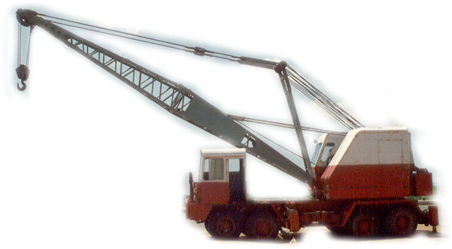
Wagon:
Maxi Crane Carrie Model 6485. Powered by Upper Works Engine. One
man operation; allcontrols operated from upper works cab; full 360
dree rotation.
Frame:
20" reinforce I-beam. All welded construction, Rigid box-type
non-extendable outriggers, front and rear, extendable outriggers,
front and rear are optional.
Axles:
Front Axles:
Solid cast steel-oscillating type, Hinded blocks furnished for suse
when absolute rigidity is required.
Rear
Axles:
Alloy steel axles with heavy duty tandem bogie.
Hubs:
Front duals are mounted on fee-wheeling differenting type hus to
permit independent rotation of outer and innter wheel,
Tyres:
Front 4 tires
12:00 x 24 - 16 ply
Rear 8 tires 12:00 x 24 - 16 ply
Breakes:
Service Brakes:
Air brakes-rear wheels only standard. 16-1/2" duaneter 7"
wide Optional air brakes for front 16-1/2" duaneter 4"
wide.(inside wheels only).
Parking
brake:
Two safety type spring set--air released units are standard. Two
additional units optional. Located between service brake chamber
and its mounting bracket.
Steering:
Power Hydraulic with heavy duty cylinder
Transmission:
Maxi Heavy Duty 900- S series Transmission, Selective 2 speed heavy
duty unit. All shafts mounted on anti friction bearings. Gears enclosed
in an oil tight housing. Air actuated gear shift.
Methoed
of Driver:
Powered by upper works engine through swing propel clutches through
vertical propel shaft with shain coupling to 2 speed transmission
in carrier, thence to rear drive wheels by chain drive.
Travel
Speeds:
Two speeds to 4 MPH.
Mounting
Data:
The Material to be located in upper works cab for th eoperating
of the wagon is furnished by Crane Carrier Corp. with the Wagon
Swing gear roller path and vertical propel shaft
furnished by bycyrus-Erie Company. |