| Superstucture
Frame |
fabricated
from high tensile steel plates and section, Mechanical superstruture
lock, operated from cab. |
Carrier
Frame |
High
strength steel, all-welded heavy duty box- section designwthintegral
outrigger housings. |
| Boom Derricking
System |
Single
double-acting hydraulic ram mounted on large diameter bushes. Fitted
with combined cartridge typre externally mounted hydraulic lock
& counterbalance valve to prevent ram collapase in the even
of hydraulic failure and provide positively controlled derricking
out. |
Carrier Drive |
4 x 4 / 4 x 2 wheel
drive with 4 weel steer. |
| |
|
Outfriggers |
Four
hydraulically operated telescopic graded outrigger beams with vertical
hydraulic jacks fitted with hydraulic lock valves. Vertical jacks
fitted with removablem, stowable outrigger feet. Outrigger controls
located in operators cab independent control of all outriggers with
individual beam and jac operation. |
| Boom Angle |
Maximum 76 dree,
minimum (-) 2 dree. |
|
|
| Derricking speed |
Maximum
to minimum radius 45 seconds (unladen). |
Engine |
Suitable
diesel engine of adequate horswepoer. |
| |
|
|
|
| Slew System |
Gear
type hydraulic motor driving apinion through a double reduction
gear unit. The pinion meshes with an internally cut slew ring. 360
dree smooth and precise continuous rotation. Free slew facility
provided |
Transmission |
Engine
mounted torque converter driving separate powershift trasmission
having 6 speeds equal forward and reverse, with high-low range shift
Oil cooler maintainssafe operating temprerature of transmission. |
| Slew Brake |
Spring
applied, hydraulically released multi-plate brake. |
|
|
Slew Speed
|
Slew speed limited
to 2.0 rev/min (unladen) for controlled operation.
|
Fuel Tank Capacity
|
273 Liters. |
Slew Ring
|
Internal
rack slew ringh grease packed and sealed fro long ife. Mounted on
precision machined surface to prevent distrition of the slew ring
bearing.
|
|
|
| |
|
Hydraulic Pumps
|
Three
gear pumps two in tandem, one single driver from power take offs
mounted on torque converter.
|
hoist System
|
Gear
type hydraulic motor driving a grooved hoist barrel via reduction
gear unit. Fitted with conunterbalance valve for controlled lowering
of the load. 13 mm diameter non-spin hoist rope. Limit Switch to
prevent over-lowering.
|
Hydraulic System
|
Hydraulic
overload valves protect pumps and crane structure from excessive
hydraulic oil pressures. Oil cooler maintain safe operating temperature
of hydraulic system.
|
Hoist Brake
|
Spring spplied,
hydraulically realsed multi-plate brake.
|
Hydraulic Oil Tank
Capacity
|
273 Liters. |
Line Speed
|
Top layer 75 m/min
(unladen)
|
Front Axle
|
Steering/driving
axle with defferential and hub reduction solidly mounted to carrier. |
| |
|
Rear Axle
|
Steering/drive
axle with differential and hun reduction. Mounted in fabricated
cradle pivoted at the centre of the carrer frame. Oscilliation locks
operated from cab. |
Maximum Fall Hookblock
4 sheave
|
28
|
Steering |
Hydraulically
powered steering to front axle by normal automotive steering wheel
in operator's cab . Independent hydraulically powered steering to
rear axle by switch in operator's cab tro permit crabbing or reduced
turning circle. |
| |
|
|
Rear
steering control mounted on side of carrier allows wheels to be
centralised ( and pinned) for road travel. |
Operator's Cab
|
Totally
enclosed steel construction full vision type tropical cab. Ergonomically
positioned joystick levers on either side of seat control all craning
motions. Insrumentation loacted on console at operator's right hand
side. Seat adjustable on slides. Automotive type steering wheel
multi-position steering column with foot controlled adjuststment.
All windows fitted with toughhende dsafety glass. Lockable sliding
door, cab interior light. Pantography type electric wiper to front
windscreen. Electric horn and fan. |
|
Automatic
reversing gear ensures correct steering wheel control regardless
of position of supersttructure relative to carrier. |
| Crane Controls |
Joystick
operating controls for slew, telescoping. Hoisting and derricking,
with independent or simulataneous operation of crane motions. Engine
speed governed bby pedal control Electric rocker switches fro control
of hydraulic outriggers Overlower limit override switch. |
Service |
Foot
operated compressed air over hydraulic pressure brakes. |
| |
|
Parking and Emergency
|
Spring operated
air released transmission brake. |
| Control Valves |
All
control valves located in a module mounted on side of superstructure
offering easy accessiblitiy. Spring-centred spool valves operated
by joysitck control levers from sperators compartment. Eeectro-hydraulic
solenoid valves contro. Hydraulic outriggers. |
Electrical Equipment |
2
+ Volts starting equipment. |
| |
|
Finish |
Painted
in all yellow with black sliding boom sections. |
Travel Controls
|
Sieering
wheel operates a rotary meter and servo valve to control the front
axle. Steering column adjustable for optimum driving/operating position
. Independent hydraulically powered steering of rear axle by twin
switches in operators cab to permit crabbing or reduced turining
cirlcle. Gear shift mounted on steering column. Service and parking
brake controls. |
Tool Kit |
Standard
maintenance tool kit. |
| Cab |
Audible
and visual warning for engine and torque converter temperature and
pressure and brake circuit air pressure. Visual warning for alternator,
raar steer, parking brake and directional indicators. Air pressure
guage and engine hourmeter gauge provided.
|
Wheels and Tyres |
16.00 X 25 X 28 PR |
| Chassis |
Gauges for engine
temperature and pressure and torque converter oil pressure provided. |
Spare Wheel and tyre |
To suit tyre size fitted. |
| |
|
|
|
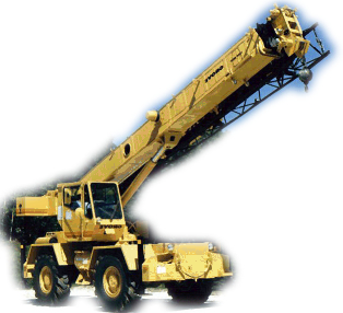
| Telescopic Boom |
Fabricated from
high tensile steel plates wih internal and exernal welds. Adjustable
and easily replaced nylon side wear pads. Fulcrum pivot points bushed
for logn life. Hydraulic lock and conunterbalance valve fitted to
prevent boom collapse in the even of hydraulic failure and to provide
positively controlled boom retraction. |
|
|
| |
8.00m to 19.00
m centres 3 section fully powered, fully synchronised boom by means
of a single double-acting aram and lacing chain to ensure proportional
telescoping of boom sections under single joystick position control. |
|
|
| Boom Capicities |
Boom telescoping
capacities are determined by boom angles and other factors and it
is safe to attempt to telescope any load within the limits of the
capacity table. |
|
|
| |
|
|
|
SAFETY SYSTEM
|
|
|
|
| Safe Load Indicator |
Provides radius
and hoom load indication, with visual indication of approach to
overload and visual and audible indication of overload condition.
Motion Cut Equipment operated by safe load indicator, cuts derricking
out, telescoping out or hoisting motion when overload condition
is obtained. |
|
|
| Limit Switch |
Pendant overhoist
limit switch at boom head and/or lattic extention.
|
|
|
| OPTIONAL EQUIPMENT |
|
|
|
| Telescopic Boom |
8.50, to 14/7
m centres 2 section fully powered boom by means of a singhle double-acting
ram. |
|
|
| Lattice Boom |
7.20 centres
swing roung easy erected lattice |
|
|
| Extension |
boom extension
to give a maximum conbinbation of 26.20 m |
|
|
| Boom Marker Light |
|
|
|
Floodlight
|
|
|
|
| Rotating Beacon |
additional visual warning device fitted
to roof of operator's cab |
|
|
| Man Carrying Basket |
With space for
two men, mounted at boom headm, incorporting articulation with locking
and damping system safety features include emergency cranning engine
stop button. |
|
|